Publish by :
arielk ,
The :
21/10/2020
at
08h 26min 02s

 par sms")


Le téléphone portable est une invention révolutionnaire du siècle. Il a été principalement conçu pour passer et recevoir des appels et des messages texte. Dans ce projet, nous construirons un système domotique, où l'on peut contrôler les appareils ménagers, en utilisant le simple téléphone GSM , simplement en envoyant des SMS via son téléphone.
Dans ce projet, Arduino uno est utilisé pour contrôler l'ensemble du processus. Ici, nous avons utilisé la communication sans fil GSM pour contrôler les appareils ménagers. Nous envoyons des commandes comme «LAMP1 ON», «STATE» et ainsi de suite pour contrôler les appareils électroménagers AC,et avoir leurs differents etats. Après avoir reçu des commandes données par le telephone de l usager via GSM, le microncontrolleur envoie un signal aux relais, pour allumer , éteindre les appareils ménagers ou renvoyer l etat de ces derniers a l usager .
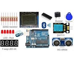
II. MATERIELS UTILISES ET COUT

Veuillez cliquer sur les images pour plus details ( couts , boutique)
|
Matériel |
Image |
prix |
|
carte arduino uno |
|
8000 |
|
Module GSM GPS A7 (AI THINKER) |
|
16000 |
|
Plaque à essai |
|
1500 |
|
Leds |
|
100 |
| cavaliers arduino (mâle femelle) |  |
500 |
| resistances de 330 ohms |  |
100 |
| relais |  |
1200 |
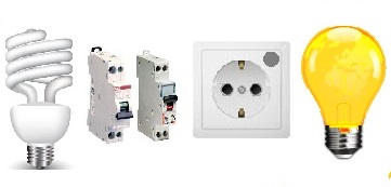
| Lampe a incandescence |  |
300 |
| Douille electrique |  |
250 |
| Batterie LIthium 3000 mah |  |
3500 |
| TOTAL | 31450 FCFA |
III. LOGICIELS ET BIBLIOTHÈQUES UTILISÉES
1 . Logiciels
2. Bibliothèques
3. Extras
Une carte sim avec credit de communication (au minimal un forfait sms par mois ou par semaine)
IV. FONCTIONNEMENT
1. Principe
Dans ce projet, la carte arduino est utilisé pour contrôler l'ensemble du processus avec un module émetteur récepteur GSM . le module GSM est utilisé pour envoyer les informations tel que l etat des appareils à l'utilisateur par SMS et pour envoyer les commandes a distance tel que "LAMP1 ON". Nous avons utilisé le module trois en un ( GPS GPRS GSM A7 AI THINKER ).

2.schemas
Les connexions de circuit de ce projet sont simples et sont illustrées dans l'image ci-dessous.
| carte arduino uno | module GPS GSM A7 Ai thinker et autres |
| 11 | PWR_KEY |
| GND | GND |
| VCC | V_BAT |
| 4 | U_TXD |
| 5 | U_RXD |
| 10 | led_vert // mode gsm ok |
| 9 | led_rouge // demarrage du module ok |
| 8 | led_jaune // prise electrique |
| 7 | relais 5v ( lampe electrique 220v ) |


V. PROGRAMME
//#include
#include
#include
#include

SoftwareSerial GSMmodule(4, 5);
#include
#include
#define DEBUG true
const int POWER_ON=11;
const int lampPin = 7;
const int LED_A7_ON=9; //led red
const int MODE_NORMAL=10; //led green
const int MODE_CRITIQUE=8;  // led yellow
const int BUZZER_SIRENE=12;  // buzzer
const int capteur_D = 6;
const int capteur_A = A0;
int val_analogique;
unsigned long previousMillis = 0;
const long interval = 200;
unsigned long t1,t2,t3;
int ledState = LOW;

//TinyGPSPlus gps;
//double latitude, longitude;
int count1=0;
String textMessage;        // Variable to store text message
String lampState;           // Create a variable to store LED state
Neotimer mytimer = Neotimer(1000);
Neotimer mytimer2=Neotimer(1000);//apres 1 sec
void setup()
{
  Timer1.initialize(100000);
  Timer1.attachInterrupt( timerIsr );
  attachInterrupt(0,reset_t0, RISING);
  Serial.begin(9600);
  GSMmodule.begin(9600);
  delay(1000);//initialize communication

  pinMode(POWER_ON, OUTPUT);
  pinMode(LED_A7_ON, OUTPUT);
  pinMode(MODE_NORMAL, OUTPUT);
  pinMode(MODE_CRITIQUE, OUTPUT);
  pinMode(BUZZER_SIRENE, OUTPUT);
  pinMode(3,OUTPUT);

  pinMode(capteur_D, INPUT);
  pinMode(capteur_A, INPUT);

  digitalWrite(POWER_ON, 1);
  digitalWrite(LED_A7_ON, 0);
  digitalWrite(MODE_NORMAL, 0);
  digitalWrite(MODE_CRITIQUE, 0);
  digitalWrite(BUZZER_SIRENE, 0);
  digitalWrite(3, 0);//broche 3 interruption
  Serial.println("Demarrage du module A7 AI Thinker en cours ...");
  delay(3000);
  digitalWrite(POWER_ON, 0);
  digitalWrite(LED_A7_ON, 1);
  delay(1000);
  //delay(10000);

  //baudrate();
  Serial.println("Demarrage du module A7 AI Thinker OK");
  //sendData("AT+RST=1 ",1000,DEBUG);
  //delay(100);
  sendData("AT+CMGF=1\r",1000,DEBUG); // AT command to set GPSmodule to SMS mode
  delay(100); // Set delay for 100 ms
  sendData("AT+CNMI=2,2,0,0,0\r",1000,DEBUG);// Set module to send SMS data to serial out upon receipt
  delay(100);
  Serial.println(" module reset ok ...");
  //Serial.println("Mode GPS  OK");
}

void loop()
{
   if(mytimer.repeat(2)){
  Serial.println("GSM mode start...");  //Print test in Serial Monitor
  sendData("AT+CMGF=1\r",1000,DEBUG); // AT command to set GPSmodule to SMS mode
  delay(100); // Set delay for 100 ms
  sendData("AT+CNMI=2,2,0,0,0\r",1000,DEBUG);// Set module to send SMS data to serial out upon receipt
  delay(100);
  Serial.println(count1);
  ++count1;}

  init_serial();
  capteur(50); //apres 5 sec de pluies on envoi le sms
  GSM_WAIT_COMMAND();
  //On_Off(MODE_CRITIQUE,100);
  //Serial.println(t1);
}


void init_serial()
{
    if (Serial.available() > 0)
    GSMmodule.write(Serial.read());

  if (GSMmodule.available() > 0)
    Serial.write(GSMmodule.read());

  if (GSMmodule.available() > 0) {
    textMessage = GSMmodule.readString();
    Serial.print(textMessage);
    delay(10);}
}


String sendData(String command, const int timeout, boolean debug)
{
    String response = "";
    GSMmodule.println(command);
    long int time = millis();
    while( (time+timeout) > millis())
    {
      while(GSMmodule.available())
      {
        char c = GSMmodule.read();
        response+=c;
      }
    }
    if(debug)
    {
      Serial.print(response);
    }
    return response;
}


void sendSMS(String message) {
  //mytimer2.repeatReset();
  // REPLACE THE X's WITH THE RECIPIENT'S MOBILE NUMBER
  // USE INTERNATIONAL FORMAT CODE FOR MOBILE NUMBERS - for example +237 is international code for Cameroon
  GSMmodule.print("AT+CMGS = \"+237680606206\"\r");
   //GSMmodule.print("AT+CMGS = \"+237683039865\"\r");
  delay(100);
  // Send the SMS
  GSMmodule.print(message);
  delay(100);
  Serial.println(message);

  // End AT command with a ^Z, ASCII code 26
  GSMmodule.println((char)26);
  delay(100);
  GSMmodule.println();
  // Give module time to send SMS
  delay(5000);

}


void On_Off(const int ledPinx,const long intervalx){
    unsigned long currentMillis = millis();

  if (currentMillis - previousMillis >= intervalx) {

    previousMillis = currentMillis;
    if (ledState == LOW) {
      ledState = HIGH;
    } else {
      ledState = LOW;
    }

    digitalWrite(ledPinx, ledState);
  }
}


void GSM_WAIT_COMMAND(){
  if ((textMessage.indexOf("On") >= 0)||(textMessage.indexOf("disjoncteur on") >= 0)) {
    // Turn on relay and save current state
    digitalWrite(lampPin, HIGH);
    lampState = "ON";textMessage = "";
    String message = "Votre disjoncteur est  " + lampState;
    sendSMS(message);
  }
  if ((textMessage.indexOf("Off") >= 0)||(textMessage.indexOf("disjoncteur off") >= 0)) {
    // Turn off relay and save current state
    digitalWrite(lampPin, LOW);
    lampState = "OFF";textMessage = "";
    String message = "Votre disjoncteur est  " + lampState;
    sendSMS(message);
  }

  if ((textMessage.indexOf("etat systeme") >= 0 )||(textMessage.indexOf("state") >= 0)) {
    if (digitalRead(lampPin) == HIGH )
    {lampState = " EN MARCHE ";}
    else
    {lampState = " EN ARRET ";};

    String message = "Votre disjoncteur principal est  " + lampState
    +" et le capteur de pluie indique : "+ String(val_analogique);
    sendSMS(message);
    textMessage = "";
  }
}


void timerIsr()
{
  t1=t1+1;
  t2=t2+1;
  t3=t3+1;
}

void reset_t0()
{ //a=1;
  t1=0;
}
VI. LA CONCRÉTISATION
1.images de realisation


VI. REALISATION
2.Videos de realisation